

Citation: Hall M, Ullbrand B, Schmidt M, “Application of CFD in the Development of a Wearable Bolus Injector” ONdrugDelivery Magazine, Issue 107 (May 2020), pp 44-48.
Marcus Hall; Björn Ullbrand and Claus Schmidt Møller, describe the use of computational fluid dynamics (CFD) as the primary design and analysis tool in the development of a wearable bolus injector.
The Subcuject subcutaneous wearable bolus injector (WBI, Figure 1) is a small and very cost-effective alternative to the complex solutions on the market today and in development, without electronic components and based on a prefilled glass cartridge (e.g. 3 mL ISO standard). Due to the simple fluid mechanical principle, the device is suitable for cold storage and for one-time use.

Figure 1: Subcuject’s wearable bolus injector.
REQUIREMENTS
Given the substantial dose volumes administered with WBIs, the delivery must necessarily be slow to avoid pain – thus requiring a long time to complete. At the same time, the drug may be highly viscous (resistant to flowing). Combined, these factors lead to a wearable device that needs to provide a low flow rate using a high force (or pressure) for a relatively long time. This can be achieved in complex and costly electronically controlled pump driven devices.
But a more cost-effective solution to meeting these requirements is an osmotically driven injector (Figure 2) as this offers high force, slow actuation and a simple design at a low cost. Lacking electronics and batteries, an osmotic drive is also more environmentally friendly than electromechanical solutions when disposed of after single use.

Figure 2: The wearable bolus injector components, including the drive module.
Osmosis uses the principle that a solvent – normally fresh water – in a solution consisting of water with a dissolved salt, moves through a semipermeable membrane from the side with lower salt concentration to the side with higher salt concentration. This process takes place even though the fluid pressure on the side with higher salt concentration exceeds the pressure on the lower salt concentration side. The flow of water can then be used as the drive module in a WBI (Figure 3).

Figure 3: Principles of the osmosis drive module.
Prior to activation of the WBI, chambers on both sides of the membrane contain fresh water. The salt is stored in a container (pouch or glass vial) in the chamber on one side. The drive module is activated by rupturing the salt container, releasing the salt into the fresh water and thereby creating a saltwater solution. This initiates the osmosis and water moves from the freshwater side of the membrane to the chamber that now contains salt water. This inflow of water can generate a high pressure and moves a plunger in a cartridge which injects the dose into the patient.
However, when using osmosis as a driving mechanism, some design challenges arise – such as designing the osmotic drive module in order to minimise the module’s sensitivity to the membrane’s physical orientation in relation to gravity. As the solvent dilutes the salt solution when it permeates through the membrane, it is not immediately mixed into the solution and thus a situation where there is mainly solvent and no salt close to the membrane on either side (concentration polarisation, Figure 4) may occur – significantly reducing the osmotic potential and thus the driving force.

Figure 4: CFD – initial model flow rate showing, for example, a high degree of concentration polarisation.
This is particularly true if the patient places themselves in a position where the membrane is horizontal and the salt solution is below the membrane, as in this case the fresh water acts as a barrier between the salt solution and the membrane. A non-flat membrane could potentially be used to circumvent this problem but, as this introduces difficulties in manufacturing of complete devices, it was decided that WBI development should focus on the use of flat membranes.
In addition, as part of normal operation, the solvent slowly dilutes the salt water and this, over time, reduces the rate of osmosis during the injection. For a simple, predictable and robust design, these challenges need to be overcome by the geometry and overall construction of the device.
CHALLENGE THE CHALLENGES BY USING CFD
Gaining pace in the late 1960s aircraft industry, computational fluid dynamics (CFD) is a numerical method for simulating fluid flow and thermal behaviour in and outside all forms of physical object, such as vehicles and devices – including medical ones. Among many things, CFD is used to predict phenomena such as the natural and forced convection of fluids, mixing, pressure drops, etc.
To aid in evaluating the WBI concept and optimise performance, Subcuject engaged specialist CFD consultant Validus Engineering, to employ CFD as the primary design and analysis tool in the development of the WBI from initial concept through to fulfilling the inventor’s design goals – including robustness, behaviour and predictability.
METHODOLOGY AND CALIBRATION
“Much of the development effort was focused on identifying geometry and solutions that would prevent a barrier effect with low osmotic potential over the membrane and maintain a high concentration of salt in contact with the membrane.”
Osmotic pressure can be defined as π = iMRT (Van’t Hoff equation) where R is the universal gas constant, T is temperature, M the molar concentration of the solute and i the Van’t Hoff index. The freshwater flux in forward osmosis is Jw=A(Δπ-P) where A is the semi-permeable membrane permeability, Δπ is the differential osmotic pressure across the membrane and P is the static pressure at the membrane.
In the CFD model, only the salt solution side of the membrane is modelled and the freshwater flux is defined as an inlet boundary condition depending on the salt concentration next to the membrane; there is no need to simulate the freshwater side as this is always only fresh water. Since the osmotic membrane is not part of the model but only the flux through the downstream side, the model is regarded as semi-empirical and requires calibration of two model constants using experimental data. The membrane permeability and the solution diffusivity, which depends on the properties of the salt, are the two constants which need to be calibrated.
Initial calibration analyses were performed for various orientations since gravity plays an important role in how the fluid moves inside the chamber. This is because the salt water is heavier than fresh water and tends to sink to the bottom. Hence, as previously mentioned, in order to provide a robust product, it is essential that the device performance is unaffected by gravitational orientation.
However, an early-concept calibration model displayed a high degree of susceptibility to concentration polarisation, as shown in Figure 4, Pos 2.
In addition, for other orientations it was seen that the flow rates were quite high during the start of the process but then were quickly reduced as the salt was diluted and – most importantly – lost out of the driven module chamber and therefore no longer in contact with the membrane.
OPTIMISATION PROCESS USING CFD
Much of the development effort was focused on identifying geometry and solutions that would prevent a barrier effect with low osmotic potential over the membrane (concentration polarisation) and maintain a high concentration of salt in contact with the membrane. Secondly, since the permeation rate in, for example, mL/min is ideally linear to the salt concentration multiplied by the membrane area, it is highly important not to “lose” salt out of the drive module as it moves the plunger. Losing too much salt solution would further worsen the already unavoidable slowdown of osmosis due to the dilution of the salt.
Each new concept was analysed for different orientations and the performance evaluated in order to optimise for a high output volume with as constant mass flow rate as possible. The simulation process complements prototype testing by means of virtual testing (digital twin) with fast turnaround times. A new or updated 3D CAD model from Subcuject was typically evaluated, with regards to performance, by Validus Engineering the following day, ensuring a high pace in the development process. In addition, and equally important, a deeper understanding of the physical processes involved was obtained as the flow could be visualised in great detail.
MITIGATING CONCENTRATION POLARISATION
Early prototypes, as seen in Figure 4, displayed a significant concentration polarisation, where the flow rate was more than halved with the drive module placed in an unfavourable orientation. This was outside the goals set for the WBI and thus required attention.
Initially various concepts were conceived and simulated, such as:
- Non-flat membrane – discarded due to manufacturing obstacles
- Mechanical stirring/mixing of the salt solution using a water wheel, impeller or Archimedes screw in various directions in relation to the membrane; driven by the outflow from the drive module
- Use of the outlet from the salt chamber to induce mixing in the chamber
- Dual membranes.
The CFD results revealed that, although some of the concepts using mechanical stirring of the salt solution to prevent concentration polarisation did offer a better-performing drive module, the improvement was too small to justify the complex mechanics required. Adjusting outlet positioning did not improve mixing in all orientations either, mainly due to the flow speeds in the saltwater chamber being exceptionally slow (only a few mm per second).
Based on numerous simulations of all proposals, the preferred approach offering the best performance in relation to the complexity of the design was to use two membranes with the salt solution in a centre chamber, flanked by freshwater chambers on both sides. If the flux through one membrane falls because of the orientation, the other membrane simultaneously compensates.
MITIGATING SALT LOSS
Early prototypes also allowed for the salt solution to immediately escape the drive module (as it drove the plunger) thus leaving less salt solution for the continued osmotic process. CFD studies of various locations of the outlet from the saltwater chamber found that all placements had drawbacks of inconsistent behaviour when the module was placed in specific (gravitational) orientations. In some orientations, mostly low-concentration solution escaped, whereas in other orientations, high-concentration salt was escaping – leading to very different osmosis rates as time progressed.
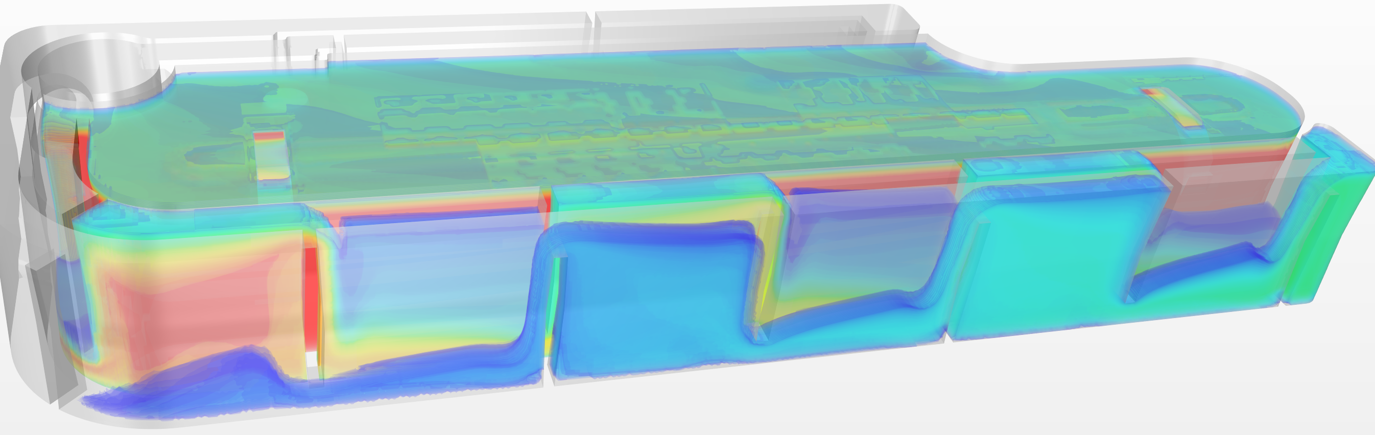
Instead, a concept using a labyrinth – making it “harder” for the solution to escape through the chamber outlet – was conceived. The basic idea behind this is for the salt container to be ruptured in a main chamber in the drive module (Figure 5, chamber is in the middle with the labyrinth on the outside. The labyrinth minimises salt water loss from the drive module). Initially this results in a smaller membrane area being in contact with salt solution but instead at a high concentration.

Figure 5: CFD – salt concentration in chamber plus meandering labyrinth concept.
As the fresh water permeates through the membrane, the salt solution is pushed from the main chamber into the labyrinth outlet. While this dilutes the salt water in the main chamber, reducing the flux here, it simultaneously increases the membrane area which is in contact with salt – thus increasing the flux in this area. Various design options for the labyrinth outlet concept were evaluated and optimised using CFD and the optimal design and ratio between initial membrane area and labyrinth membrane area was chosen.
REQUIREMENTS HAVE BEEN MET
Combining the dual membrane solution’s insensitivity to gravitational orientation with the meandering labyrinth outlet part that increases the contact area between salt and membrane as the process proceeds, was proven to be the ideal balanced solution, as seen in the mass flow graph (Figure 6). Thus the WBI offers injection flow at 1 mL/min up to 10 mL while maintaining high orientation insensitivity and optimal flow rate profile.

Figure 6: CFD – meeting the device flow rate goal.