Citation: Sørensen B, “Re-usable Electronic Autoinjector – Flexible Performance”, ONdrugDelivery, Issue 120 (May 2021), pp 44–46.
Bjarne Sørensen discusses the ability of electronically driven injection devices to cater for a broad range of liquid drug properties within a single device platform.
In a previous ONdrugDelivery article, Phillips-Medisize argued that there are several changes in the market that might accelerate a transition from disposable mechanical to electronic reusable autoinjectors. Beyond megatrends around sustainability, connectivity and self-administration of drugs, pharmaceutical companies continue to pursue broad range platform devices that can be reused across multiple drug formulations with widely varying properties. This article focuses on this aspect of electronically driven injection devices; the ability to cater for a broad range of liquid drug properties within a single platform device. Data from a mathematical model will be presented to support this hypothesis.
“The injection sequence also provides for a configurable dwell time with a specific force on the stopper to minimise dead volume before the end-of-dose signal is indicated to the user.”
Phillips-Medisize has been developing a new smart autoinjector that is small and easy to use for patients and provides a powerful and flexible platform for pharmaceutical companies. This new development presents a very different take on the challenges with injection devices that follow new agendas like connectivity and sustainability, but it also presents a powerful approach to addressing the challenges and compromises coming from autoinjectors with spring-driven drive trains.
KEY ELEMENTS OF THE SMART AUTOINJECTOR
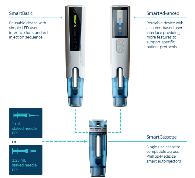
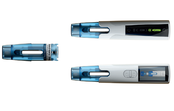
Figure 1: Key elements of the Phillips-Medisize smart autoinjector.
As shown in Figure 1, the device consists of a single-use, disposable cassette that contains the prefilled syringe and an electronic reusable device that contains all the electronics and offers product customisation through different versions of the user interface, including the possibility of a full graphical display.
Cassette
The disposable cassette, which incorporates needle safety features, can include either a 1.0 mL (all flange types) or 2.25 mL (small round flange) syringe. The cassette is discarded in a sharps container after use, as usual. It is compatible with a range of standard prefilled syringes and components, according to ISO 11040. This is a true platform opportunity for the pharmaceutical industry, as the same cassette can be used to deliver a wide range of drug products with different injection volumes and viscosities.
The cassette is made of plastic and lacks metal springs. It is significantly smaller and lighter than current disposable devices. During transport and storage, the cassette is not under any load, allowing for a minimal approach to packaging.
The cassette can be loaded with a syringe by axial insertion, and with automated locking in the cassette. Phillips-Medisize can supply cassettes in bulk or handle the complete process of fitting syringes into cassettes in a controlled environment, including serialisation, if desired. The cassette label can include a radio frequency identification (RFID) tag, readable from the device, and selected data can be submitted to a connected system.
Device
The reusable device includes an electronically controlled drive train, powered by a rechargeable battery, with Bluetooth Low Energy (BLE) connectivity options. RFID reading of cassettes is an option as well.
The device is available in two versions:
- The SmartBasic device with LEDs and audible support, which is similar to typical disposable autoinjectors but with an extended user interface.
- The SmartAdvanced device with a graphical user interface and a menu-driven operation, also including audible support. It is possible to have a custom-designed user interface, including buttons and further functionality, with this version.
Both device versions have the connectivity option embedded and can convey selected information to an app and a secure backend platform. Phillips-Medisize offers a complete connected health solution or customers can connect the devices to other systems.
“A key advantage of the motor drive is that high forces can be applied in a fully controlled manner, so it is possible to optimise delivery of even highly viscous drugs and still minimise the needle size.”
Drive Train Description
The drive system is microprocessor controlled and features a brushless DC motor that, via gearing, drives a threaded spindle. There is an encoder embedded in the motor, so the position and speed of the plunger is known by the processor. Furthermore, the processor can tightly control the applied force on the syringe, so all aspects of the plunger movement are controllable from parameter settings in the firmware of the device and can be configured to the specific requirements of the drug and therapy.
A key advantage of the motor drive is that high forces can be applied in a fully controlled manner, so it is possible to optimise delivery of even highly viscous drugs and still minimise the needle size.
The algorithm prioritises the target injection time, varying the force as required to achieve this time (up to the configured maximum force). The injection sequence also provides for a configurable dwell time with a specific force on the stopper to minimise dead volume before the end-of-dose signal is indicated to the user.
The configuration of the device during manufacturing will include the following parameters:
- Target injection time
- Maximum force applied
- Target dwell time and plunger force.
In the advanced device, the target injection time and other settings can optionally be adjusted by the patient. The battery in the reusable device is a rechargeable lithium-ion cell which can be charged from a USB port.
DIFFERENCES BETWEEN ELECTRONIC DRIVE TRAIN AND SPRING-DRIVEN DRIVE TRAIN
Electromechanical drive trains offer several potential benefits when compared with spring-driven systems. Configuration of the latter requires a delicate balance between several, sometimes counteracting, aspects whereas the important parameters of an electronically driven system can be configured to consistently deliver the target requirements, with headroom available to account for real-world variation encountered via the full system interactions, including primary container, drug, needle and injection site.
| Function | Electronic drive train | Spring driven |
| 1.0 mL and 2.25 mL compatibility | The device and cassette accommodate both 1.0 mL and 2.25 mL syringes, so it is a true platform, with sufficient power to drive both syringe sizes. | Different devices are usually required due to the increased power (approximately 4 x force if all other factors, such as needle gauge and injection time remain equal) and hence size required. |
| Engagement with the stopper |
The plunger moves at a constant injection speed, and thus engages with the stopper in a controlled manner, gradually building up the required force on the plunger to achieve and maintain the target injection speed. | At the start of an injection, the plunger is released with the full force of the compressed spring, quickly accelerating towards the stopper. At impact, the plunger strikes the stopper with a considerable impulse force that creates a shock wave in the drug and stresses within the prefilled syringe. |
| Partially filled syringes |
As above, the plunger moves at a constant injection speed, regardless of syringe fill volume, and therefore the stopper engagement is controlled and gentle across all syringe fill volumes. | In a partially filled syringe, the additional flight distance between plunger rod and plunger stopper generally occurs over the highest force profile of a compressed spring, increasing the impact and shock forces on the syringe assembly. |
| Break-loose force | The electronic drive system has a large and controlled power reserve, meaning it can overcome the break-loose force while still controlling the rate of injection immediately after stopper movement commences. | Spring-driven systems are generally sized to overcome the break-loose force but have little ability to control the rate of injection once stopper movement commences. At this point, injection rate is driven by spring-force decay versus the resistive forces of the syringe barrel and liquid flow through the needle bore. |
| Variations in siliconisation | The electronic control maintains a constant injection speed, adjusting motor current and hence plunger force to deliver a consistent injection time. Because the full force is available throughout the entire stroke, the electronic system is able to accommodate changes in resistive forces from sources such as siliconisation variations. |
As the majority of spring-driven devices use compression springs, the available force tends to decrease over the stroke length. Springs need to be sized to overcome potential resistive forces encountered throughout the stroke, such as siliconisation. Variations in these resistive forces tend to impact injection time as it is the parameter that can’t easily be controlled in spring driven devices. |
| Different drug viscosity ranges |
The electronic drive and motor system has the power to cope with very high viscosities, which can allow a thinner needle to be used in some applications. The same device can work with both low and high viscosities without any changes as the drive algorithm will adjust the force output to maintain the programmed injection time. | Spring-driven systems for high viscosity drug delivery can require large, powerful springs to be maintained in a compressed, or energised, state until activation. This places a constant high load on the plastic device body throughout transport and storage. |
| Dead volume in syringe at end of stroke | Configurable force on plunger at end of stroke, to compress stopper as required, minimising dead volume. | Dependent on remaining force from spring at end of stroke. |
| End-of-dose indication |
The end-of-dose indication is software controlled, encompassing full stroke travel, stopper compression followed by a programmable dwell time. Therefore, the audio-visual end of dose indication provides direct user feedback that it is safe to remove the injection device without a separate “hold” time. This should have the added effect of reducing “wet” injections caused by users removing the device too soon. | Typically, end-of-dose indication is provided by a mechanical sound initiated by the plunger movement nearing the end of its stroke. This typically happens slightly before the injection is complete, requiring an instruction for the user to “hold” the injector in place for a period of time before removing. Removal before the end of this time period may result in a “wet” injection. |
Table 1: Functional differences between electronic drive train and spring-driven drive train.
In Table 1, some of the key functional differences are described.
SIMULATIONS PERFORMED ON THE SMART AUTOINJECTOR AND SPRING-DRIVEN SYSTEMS
To simulate the performance of mechanical and electromechanical autoinjectors, Phillips-Medisize developed a complete dynamic model like that published by Zhong X et al (2020).1 The model assumes:
- A flight distance between the plunger rod and plunger stopper for the mechanical autoinjector of 3 mm
- An air bubble of 5 mm between the plunger stopper and the liquid in the prefilled syringe
- Injection into air (so no back pressure)
- The algorithm as embedded in the smart autoinjector.
In Figure 2, we show different key parameters for a 50 cP, 2.0 mL drug, 27GTW needle with a targeted injection time of 15 s, and for both drive train types. A spring rate of 1050 N/m for the spring-driven system was defined to suit these requirements.
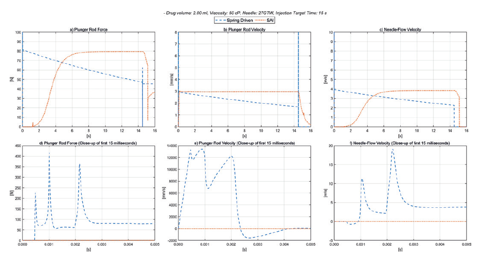
Figure 2: Spring-driven autoinjector versus smart autoinjector 50 cP.
As can be seen in Figure 2a (plunger rod force), the electronic autoinjector can deliver a soft controlled engagement with the stopper, and a constant force on the plunger throughout the injection. During the configurable dwell time, the force on the stopper can be optimised to minimise the dead volume – shown here as 35 N. It is also evident that the force available from the spring-driven system is significantly different at the start and end of the stroke.
Figure 2b (plunger rod velocity) shows the constant plunger speed of the smart autoinjector, and the declining plunger speed for the spring-driven one. Figure 2c (needle-flow velocity) shows the constant flow in the fluid path of the electronic drive train, and the declining flow rate of the spring-driven version.
As shown in Figures 2d, 2e and 2f, for the initial phase of the injection, the forces from the spring-driven plunger on impact with the plunger stopper, after the free flight distance, are approximately three to four times the nominal plunger force calculated during the actual injection. It is these higher forces that are likely to limit the performance of the drive train to deliver the drug without risk of damaging the prefilled syringe. For the electronic drive, the nominal force on the plunger stopper after the free flight gradually increases as the air bubble is compressed and then remains constant as the plunger stopper is driven along the barrel.
The additional force headroom for the electronic drive train enables a potentially shorter injection time in this example and increases the ability to work with higher viscosities. Furthermore, it is more straightforward to optimise the setup for the required target injection time with the minimum possible needle size. The maximum force applied to the syringe can be configured to accommodate the specification of the actual syringe assembly which, in most cases, determines the overall limitations of the system. Given the large headroom, there are none of the typical issues with potentially excessive break-loose force or stalling plungers due to differences in siliconisation.
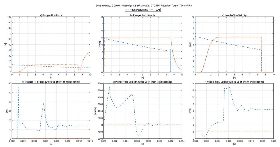
Figure 3: Spring-driven autoinjector versus smart autoinjector 4.5 cP.
“Beyond the sustainability and connectivity benefits offered by the smart autoinjector, it is evident from the simulations presented here that the electronic drive train offers performance and platform benefits for the delivery of injectable drugs.”
Figure 3 shows the same curves but for a 4.5 cP, 2.0 mL drug with 8 s injection time, and again for both drive train types. A spring rate of 172 N/m for the spring-driven system was defined to suit these requirements. The only difference to the electronic drive train used for the 50 cP liquid and the 4.5 cP is that the target injection time was set to 8.5 s, with the other device parameters and settings unchanged, showing the superior flexibility of the electronic platform. The same settings in the smart autoinjector can be used for 1.0 mL syringes and 2.25 mL syringes.
Given the very different delivery requirements, the spring-driven drive train will require different spring rates of 1050 N/m and 172 N/m respectively, resulting in further development work to determine and verify the functionality for different drug properties and parameters such as break-loose force, changes in siliconisation, mechanical stability of the device and all other relevant design considerations
SUMMARY
Beyond the sustainability and connectivity benefits offered by the smart autoinjector, it is evident from the simulations presented here that the electronic drive train offers performance and platform benefits for the delivery of injectable drugs. The approach offers a wider range of flexibility and suitability compared with traditional spring-driven autoinjectors, which are likely to be more sensitive to changes in drug delivery parameters, and thus also require more development efforts and fine-tuning to optimise the design for each new application.
The motor control algorithm, as developed for the smart autoinjector firmware, enables swift configuration of the system to the selected parameters such as injection time and maximum applied force on the plunger. The smart autoinjector provides a powerful platform device featuring a very high degree of flexibility on critical parameters, and wide suitability as the system can be used for both 1.0 mL and 2.25 mL syringes.
REFERENCES
- Zhong X et al, “An experimentally validated dynamic model for spring-driven autoinjectors”. Int J Pharm, 2020, 594:120008.